Simon Lederhilger

My academic and personal webpage
Email: no current email






The failure of the medial axis
The airfoils you find on the internet are often polygons, which I saw as an obstacle when I wrote my master's thesis on the the vortex lattice method, applied to wind turbines.
For this method, you discretize the blades of the wind turbine into flat lifting surfaces, using the mean camber line as the basis for the resulting panels.
The vortex lattice method isn't really concerned with the displacement of the air flowing past it due to the physical thickness of the blades themselves, so this approximation of the blades as panels is fine.
The problem I was faced with was how I was supposed to extract the mean camber line from the finite number of points provided to me by some dat-file I found online.
You see, for my bachelor's thesis, I was told to use the SD7032 profile as the exemplary airfoil on which to base my analysis.
This airfoil is only found as a collection of sixty or so points that define a polygon that approximates it.1
For my thesis, I was reading many of the papers of John Hess and Apollo Smith, a paper of the former suggesting what would inspire me to pursue this topic, even though it wasn't really relevant to its main research question. This paper of Hess's, and pretty much all his papers on the topic, pertained to the representation of the wing in full for the displacement solution, but with a very similar construction of bound vorticity on the mean camber line.2 He suggests that an airfoil given as an equal distribution of points on the pressure and suction sides of the airfoil would yield pairwise vertices by which one could find a linear interpolation of the mean camber line through the midpoints of the lines connecting them, the leading and trailing edge vertices notwithstanding. Although I try to craft my writing such that one may understand what I'm talking about just by reading my text, I understand that it may be cumbersome, so here's a picture:

This is obviously a very bad approximation of the mean camber line. My first thought was that this isn't very good for the sole reason that the SD7032 profile doesn't actually have an equal number of points on the suction side as on the pressure side. What I did to construct this figure was choosing a somewhat coherent collection of points on the suction side, and then try to match those points in abscissal value from among the pressure side points to the best of my ability. To address this issue, I thought you could use a sort of first order approximation in the sense that you can draw a straight line from each vertex to the ordinately opposite side of the polygon, and construct the mean camber approximation in a similar manner to Hess. My second thought was that this could obviously be done much better with splines, and so I went to speak with Mike, whom I reckoned to know a thing or two about such things. Drawing my polygonal airfoil on the blackboard in his office, he said something along the lines of "This sounds like the medial axis." And so, on this medial axis tangent I went on workdays during which I ought to have been preöccupied with implementing the fast multipole method to my vortex lattice solver.
My search for literature swiftly brought me before the paper titled Medial Axis Transformation of a Planar Shape by Decai Li,3 and with it came my formal introduction to the Voronoj diagram, something I had heard of in passing before. It turns out the medial axis is a subset thereof, you just have to remove the edges that terminate at a reflex vertex. I won't recite Li's entire article here, but I will provide the broad strokes, though I'll present a simpler, more digestible algorithm involving quadtree partitioning for you. Truth be told, I did get the implementation wrong the first time around in my master's thesis, which did end up in the appendix of the final draft. I'll discuss exactly why my implementation was wrong, but first a taste of the correct implementation. Here is the medial axis of the SD7032 sampled at four point increments, approximately evenly distributed for the pressure and suction sides:
Dragging the slider will increase the number of sampled points by four. Try it out!
Consider a set of ordered points $G = \{ p_0, \dots, p_{n-1} \}$, serving as the vertices of our simple $n$-sided polygon (simple here refers to nonintersecting). The edges of the polygon we label $e_i$. You can now either construct the Voronoj diagram with respect to the vertices or the edges, the former of which I erroneously chose to implement for my thesis. Either way, the Voronoj diagram of a collection of elements, be they points or edges, is the curve which is at each point equally distant from two or more elements. Clearly, a Voronoj diagram with respect to the vertices will terminate in the middle of the edges, whilst a Voronoj diagram of the edges will terminate at the vertices. This is very evident when you consider a rectangle:
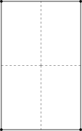
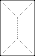
The dashed lines in the left rectangle is the Voronoj diagram with respect to the vertices, whilst the dashed lines in the right triangle is the Voronoj diagram with respect to the edges. As you can probably gather, what I did for my thesis was indeed to make the Voronoj diagram with respect to the vertices. How I managed to do this is quite simple: I had read that the Voronoj diagram was the dual to the Delone triangulation, so I just triangulated the airfoil, and found the dualby connecting the triangle circumcenters. Since edges of the triangles will sometimes coïncide with the edges of the polygon, the full Voronoj diagram of the polygon would of course have lines terminating at the edges. But I specifically wanted the airfoil mean camber line, so I paid little attention to where the lines off the mean camber line terminated. Here is the resulting full diagram of the SD7032 airfoil:

This was a complete failure, though I hadn't realized exactly why. I just thought that the medial axis worked as a poor approximation to the mean camber line for airfoils. We now understand that I'd just got lost in the interesting new fun facts and interesting pieces of mathematics around the Voronoj diagram. In immersing myself in the Delone triangulation, I had completely neglected the original insight I had gained from Li, and it would not be until I reread his article preparing to write this very entry to my weblog that I relaized where I'd gone wrong.
Li states that for a polygon with $n$ sides, and $m$ reflex vertices, the interior of the polygon will be divided into $n + m$ Voronoj polygons, whose union is the Voronoj diagram. I think this is best explained by illustration. I've recreated Li's figure 3 below. Checking the regions button will show the Voronoj polygons of the polygon edges in a darker color, and the Voronoj polygons of the reflex vertices in a lighter color. Checking the Voronoj button will draw the Voronoj edges. The medial button just removes the Voronoj edges terminating at a reflex vertex, which is what Li defines as the medial axis of the polygon.
I've made the polygon interactive, so you're free to click and drag the vertices around.
Notes
- Coördinates are found on page 122 in Selig et al. (1989).
- See figure 7a in Hess (1974).
- Although his name is often rendered Der-Tsai Lee, I prefer to transliterate names consistently using modern standards, so I have cited him based on the pinyin of the Chinese 李德財, which is Décái Lǐ. Whence Li (1982).
Bibliography
John L. Hess, The Problem of Three-dimensional Lifting Potential Flow and its Solution by Means of Surface Singularity Distribution, Computer Methods in Applied Mechanics and Engineering, 4 (1974), pp.283–319
Decai Li (李德財), Medial Axis Transformation of a Planar Shape, IEEE Transactions on Pattern Analysis and Machine Intelligence, PAMI-4 (1982), pp.363–369
Michael S. Selig, John F. Donovan, & David B. Fraser, Airfoils at Low Speeds, 1989 by H. A. Stoakley, publisher